

Introduction
This article will take an in-depth look at cold heading and cold forming.
The article will bring more detail on topics such as:
Principle of Cold Heading
Types of Cold Heading or Cold Forming Processes
Applications and Advantages of Cold Forming
And much more…
Chapter 1: Principle of Cold Forming
This chapter will discuss the definition, materials, and tooling methods used in cold forming.
What is Cold Heading?
Cold heading is also called cold forming, making these terms interchangeable. Cold heading or forming can be defined as the process of continuously forming a specific shape or design from a metal wire without adding heat. This is aided by high-speed hammers, dies, and punches.
Cold forming begins with a slug cut from a progressive coil or wire; then, the cold heading machine uses a chain of strong hammers and dies to form a part. Cold heading can also be defined as a process that applies force from a punch to the end of a metal blank in a die. The force must surpass the metal’s elastic limit or yield strength in order to permit plastic flow.
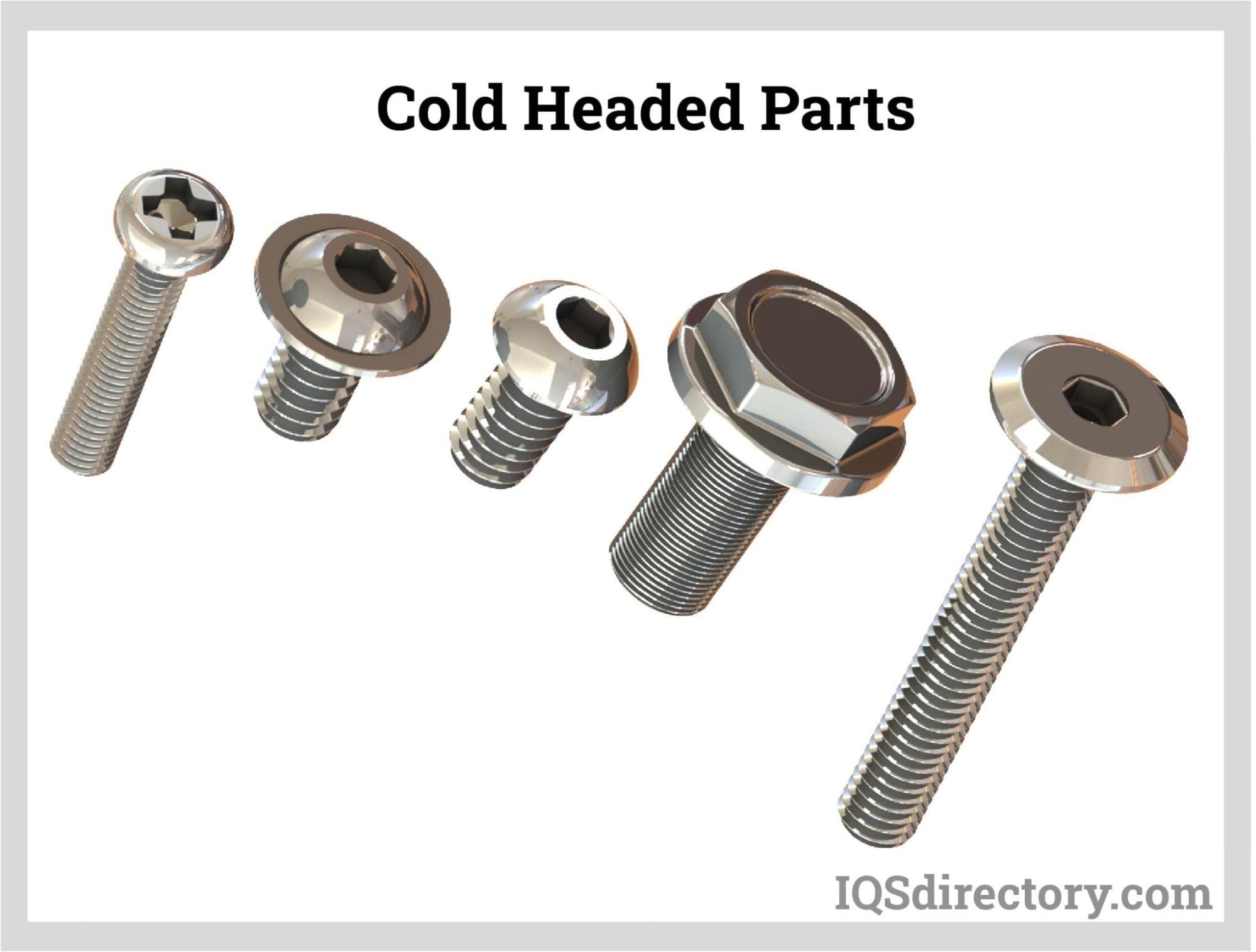
Cold heading can be considered a forging operation without the use of heat. It is performed together with other cold heading processes such as blank rolling, piercing, pointing, thread rolling, sizing, and trimming. Cold heading is also an industrial process that acts as the primary way to make metal threaded fittings and fasteners.
The cold heading process involves forging at very high speeds where the coiled wire is carefully sheared to length at room temperature and the correct pressure. Then it is moved through continuous die and tool openings to displace and shape the working metal to form the required product. The cold heading process can decrease or increase feedstock diameters and lengths and can remove small amounts of material through piercing and trimming. All cold heading processes and operations are done in a continuous, planned process.
Historically, cold heading was only used for making very simple fasteners. Currently, cold heading is an automated high-speed and multi-station method that is able to economically produce composite fasteners and other components. With the improvement of technology and growth in cold heading, the equipment has the ability to cold form parts from tougher metals, including higher-temperature alloys and stainless steels.
Materials and Tools Used in Cold Forming
All cold headers have a specific method to cut off and measure out a piece of the wire coil. The method of putting the wire inside the cold header and cutting it off often varies depending on the brand needed. Once it is inside the machine, only a cut-off knife will remain. This knife will strike the wire from a defined direction, cutting off a single piece. This process often consists of numerous parts, not mentioning the cut-off knife.
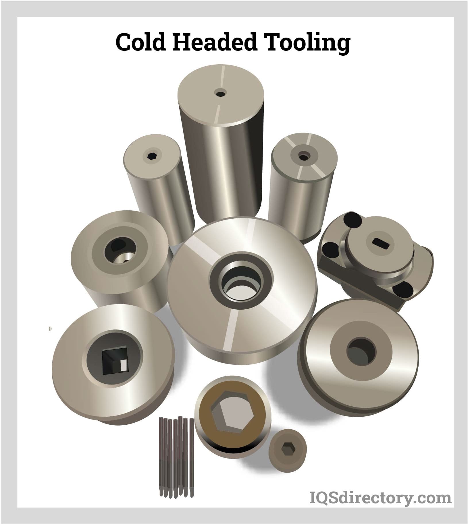
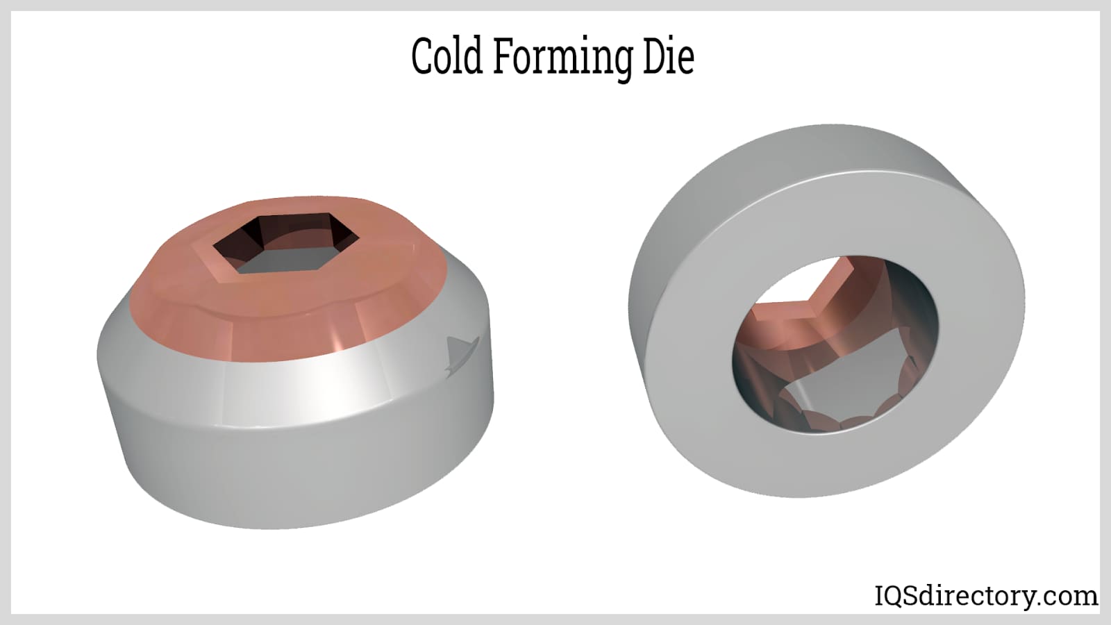
Cold Forming Dies
Since they must withstand heavier loading, dies are very large compared to punches. Dies are found on the stationary part of the cold header. Each die is usually multiple pieces. The working tool is often made in three to four different segments that define the whole working part of the die. Afterwards they are all put under intense pressure into a large, circular curved canister usually named the casing.
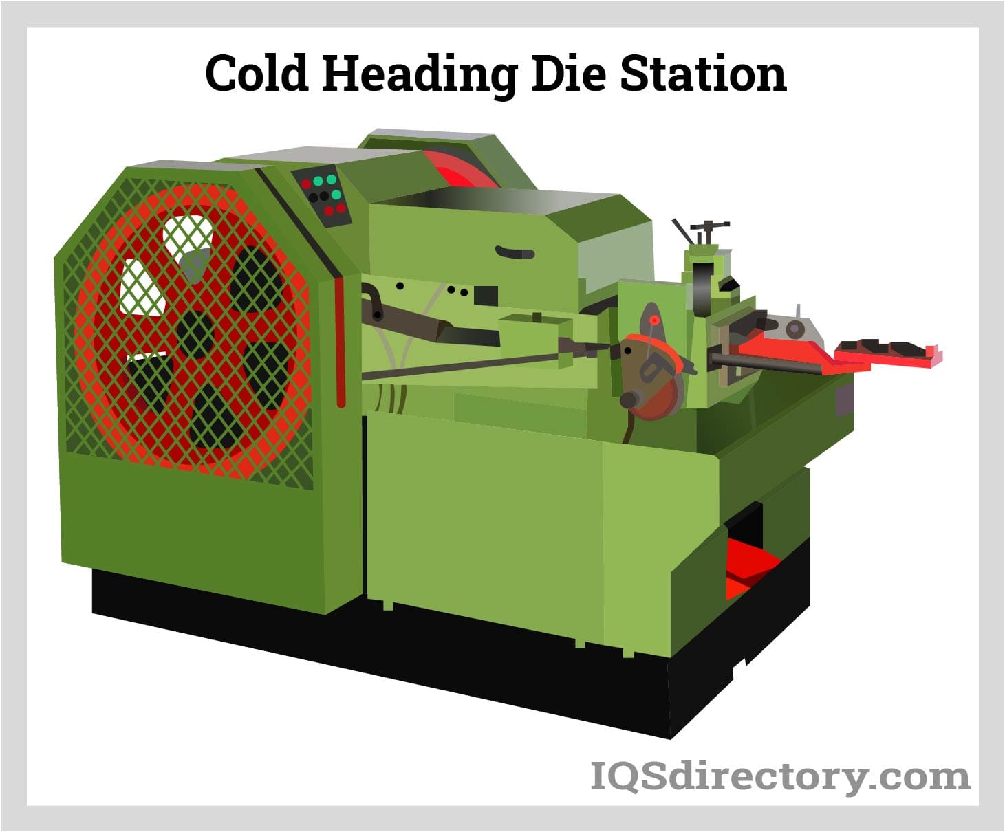
The inserted part of the die is put under intense radial pressure with each single blow. They would quickly explode and fail if they lack or do not have some form of support. To solve this problem they are forced hard into the casing. This casing is much larger and is able absorb in and disperse all the pressure building up giving integrity to the die for many parts or cycles.These die casings can be used many times before they need to be changed.
All these dies have a specific sized hole central to the axis of the tool where the part is set. Due to the high pressure that is put on parts, what stops them from shooting out through the die and out through the back of the machine? The knock-out pin system then comes into place. A chain of pins are put at the rear of the die to carry out two functions. Initially during the making portion of the stroke, they stop the part from being driven out through the back of the die. Secondly, at the last phase of the forming stroke, these pins are cast forward driving the part out of the die.
Cold Forming Punches
Punches are found on the moving part of the machine. Compared to dies, punches are smaller because they encounter less pressure during the heading process. Punches also encounter and experience great loading and must be contained in the punch casings.
These punches define the shape or design of the head for the screws. One punch will be the initial blow and the other punch will be the last blow. The punches can also be the support to a pin that pushes the part inside the die. This is usually in cases where the dies are aiding trapped extrusions or recess pins, which aid the backward extrusion to drive recess in parts.
Cold Forming Transfer
This is the last tool system in the transfer mechanism. Cold forming transfer is much simpler when on a single die, two blow machine, because there is only a single transfer necessary, which is the cut off to the die. Nevertheless, once the stepping up process is increased to multiple dies in a multi die header, the transfer mechanism becomes an important component.
The most common tooling pieces used for the transfer are the fingers or grips that hold the parts when they move from one die to the next. The fingers are often custom-made to meet the desired needs for each part. Part geometry is important in transferring a part, as parts can be very heavy. It is possible to upset the head and sometimes a large shoulder, causing the part to droop as it moves out of the die.
The person operating the die has to make sure the transfer is timed right to hold and grab the part before it completely exits the die. However, the transfer does not move the part until it is fully clear of the die. This process requires a lot of practice and experience by the setup technician to master the skill.
Machines Used in Cold Heading
The cold heading machines produce a metal blank into perfectly shaped or designed parts by making use of a reciprocating ram that forces a hammer into a preformed die. The cold heading machine is known as the stamping machine in mechanical processing and manufacturing. If the initial raw materials are not changed, the materials are designed as desired.
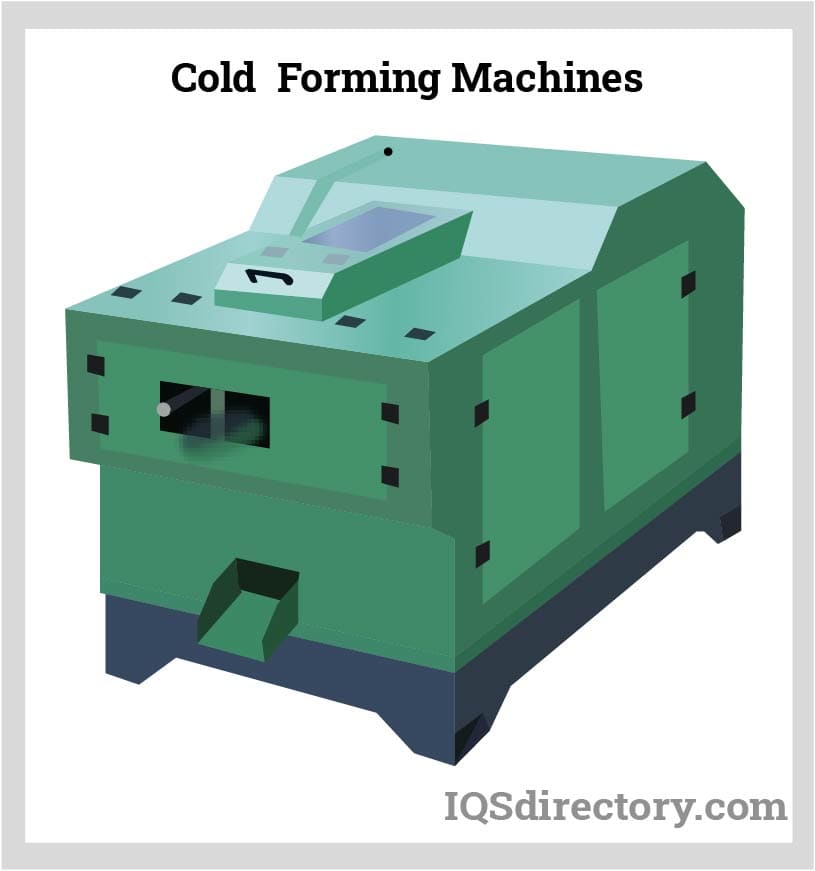
In a cold forming machine, bevel gears are paired and put on one end of the crankshaft. The driven bevel gear shaft is put on a cam gear, with a scissors slider vertically put on the roller shaft consisting of the driven roller of the cam object or device. The utility model overcomes all the encountered deficiencies of the prior art, and also the moving friction coefficient. The impact force among all components of the cutting and feeding mechanism are very small in magnitude. The smooth operation of the equipment largely minimizes the operating noise and improves product productivity and quality.
Cold Heading Operation
The process of cold heading uses high-speed automated part formers or cold headers. This equipment is capable of transforming a simple wire into an intricately designed part with very tight and repetitive tolerances by using a tooling method at speeds of 400 pieces per minute. A defined length of wire is put inside a die, and a hammer then extrudes or upsets the material into the required form.
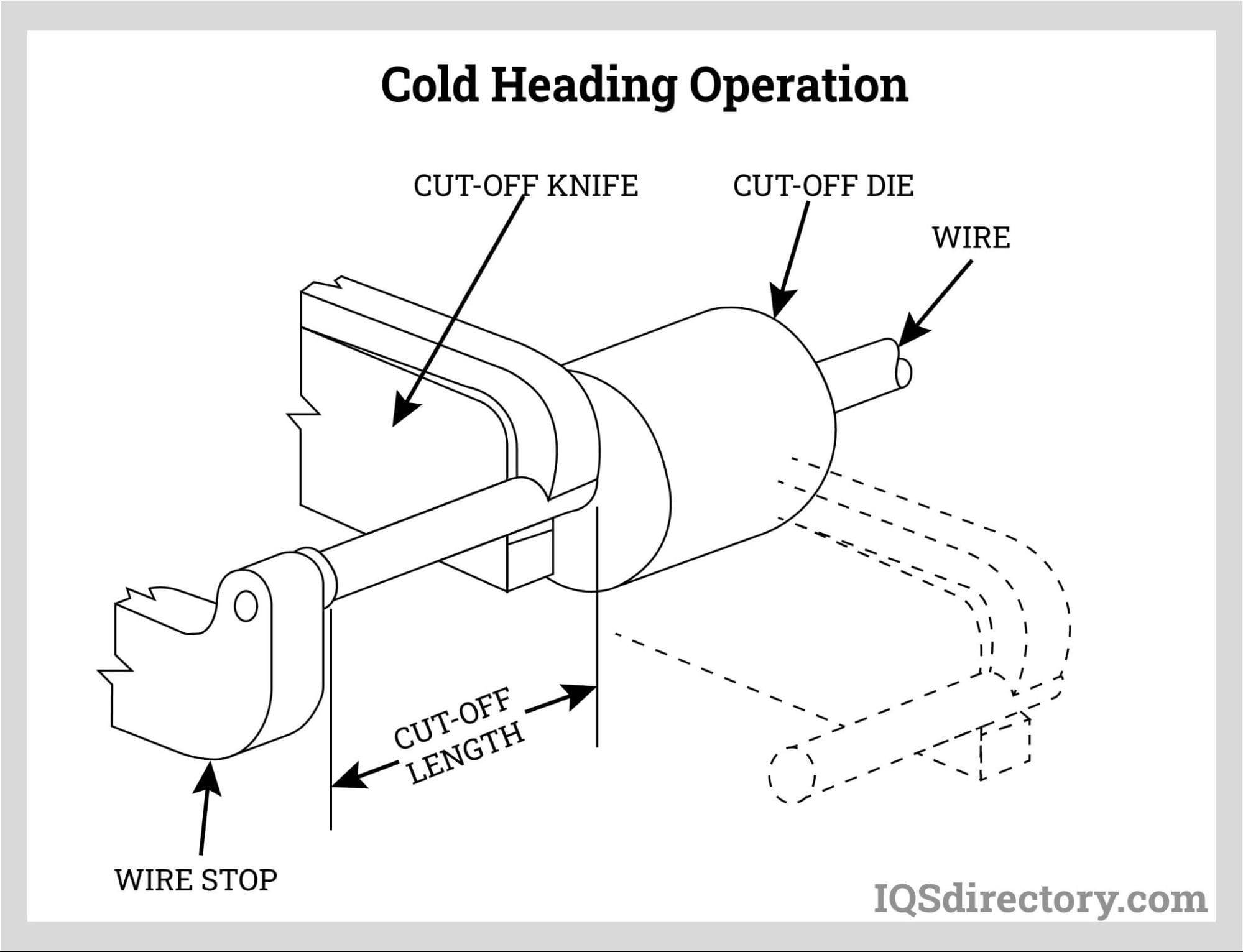
Since the process of cold heading is volume specific, and it also uses a given volume to make a final intricately designed part of the exact same volume, the material will be simply rearranged. The loss of scrap or material is very low.
Recent Developments in Cold Forming Machinery
The cold heading and cold forming machinery has recently become much more advanced. Machines are now being made with five or more dies and many features to maximize the production of both short and long parts. A single adjustment can change the feed stroke, cutter, kick out, and transfer timing functions. The CNC control gives the operator access to the required production data quickly. Immediate change setups work for both die and punch components to be set up and be adjusted when one is offline, so production time is maximized. Multi-station headers can also be used.
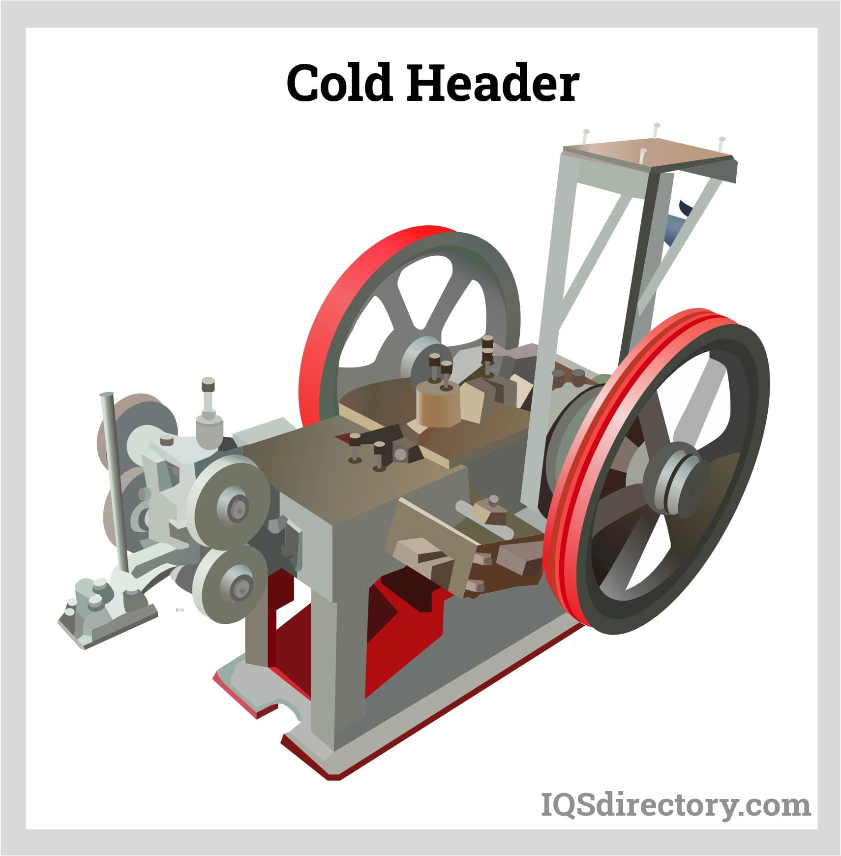
These perform a combination of extruding, upsetting, and other cold forming operations. Cold forming operations have also greatly increased heading production capabilities and rates. Increased metallurgical information and knowledge has enabled the heading and cold forming of much harder and tougher materials. Top alloy producers closely control the analysis and producing of grades to satisfy demands for greater strength and corrosion resistance in the headed part.
It is possible to have specific AISI grades made within the controlled analysis boundaries to improve cold formability where good cold heading qualities, greater performance, and subsequent second order machining performances are needed. In some cases, the analyses of the cold forming process allow for specific fastener shapes to be made more economically. Much tougher tool steel extends the lifespan of the heading dies. Producers of cold headed products do make alloys which are versatile enough to be fabricated by both machining and heading.
Chapter 2: Types of Cold Heading
Types of Cold Heading Equipment
There are two basic types of equipment used in cold heading, which are:
Part formers
Cold headers
Both make use of horizontal reciprocating rams and fixed bolsters. Cold heading equipment has a range of a single die up to as many as seven dies placed in progression, with varying cut-off sizes. The range of cold heading a manufacturer can provide depends a great deal on the number of machines they have available.
The two main components of the cold heading tooling process are dies and punches. Punches transfer the needed amount of force from the machine at hand to the material and provide close dimensional control on part features inside. The dies direct and confine the material into the desired shape and geometrical dimensions.
Types of Cold Heading Processes
Cold heading derives its name from the upsetting process.
Cold Heading Upsetting
This is the method used to make a head on a bolt or screw. Upsetting can be defined as the process which brings together materials into a unit area of the part, such as the collar or a head. Put in other terms, in the areas that are being upset, the diameter is increasingly enlarged. When using cold heading language, manufacturers say "the maximum number of diameters that can be upset."
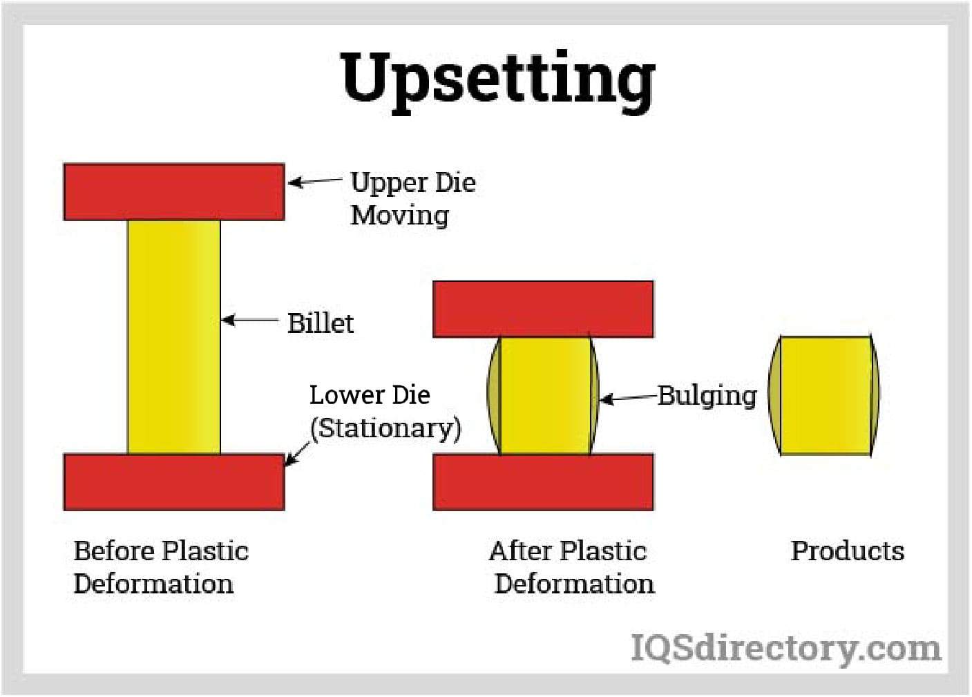
Although it looks and sounds much more complex, upsetting is a simpler way of forming. It is a simple cylinder that is cut or removed from the lengthy continuous wire coil that is put inside the machine. For the parts that will become bolts and screws, or the externally threaded ones, the cylinder is much longer than its diameter. It is possible to break the cylinder down into different sections where each section is the same diameter and height. Each division is called a diameter. Some parts are very long and skinny, such as screws and bolts, with each beginning piece of wire consisting of multiple diameter sections.
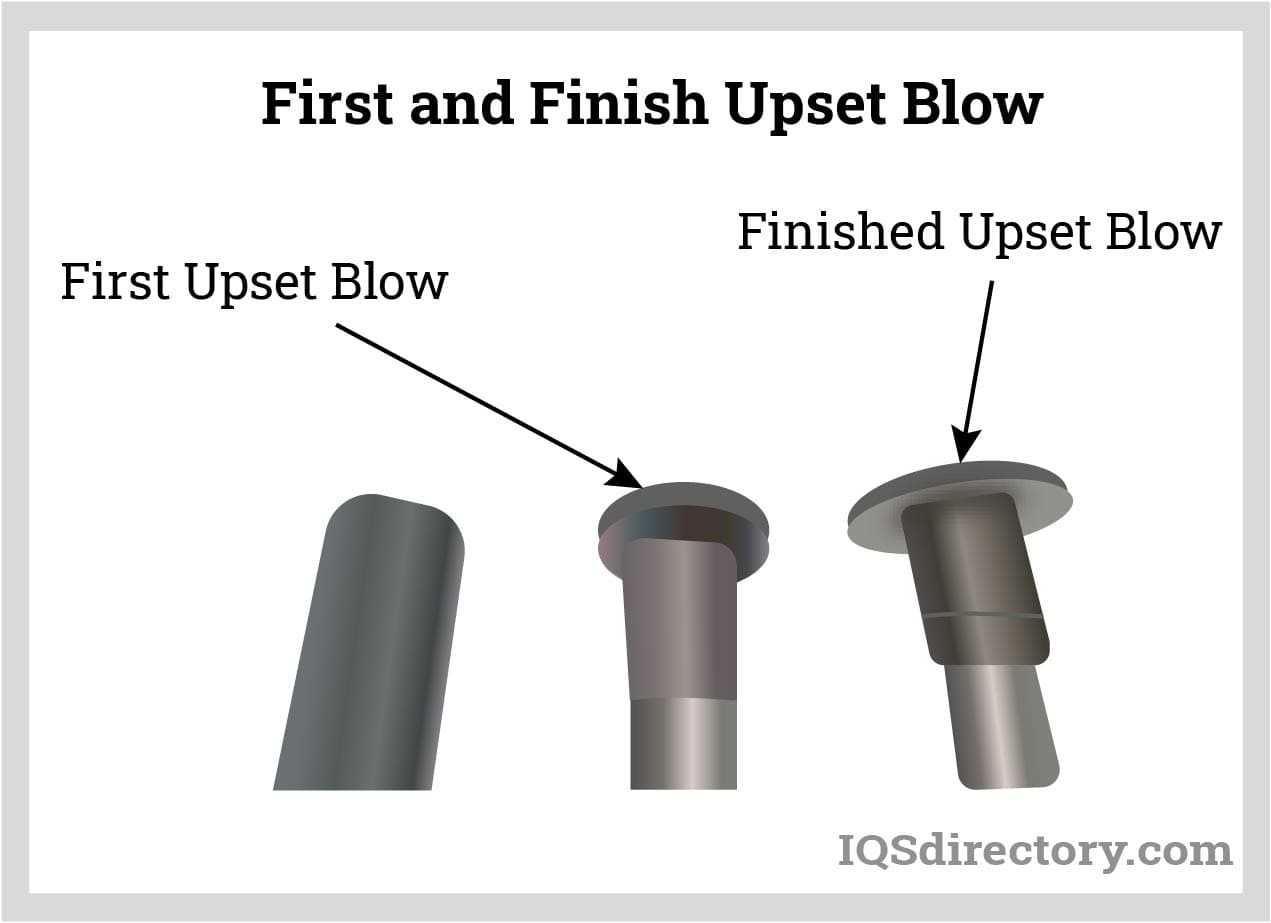
Engineers have learned over the years that only a limited portion of material can be moved or squeezed at one time before it bursts or cracks. In a cold heading environment, the limitation is roughly two percent diameters per each strike. Many bolts heads or screws have more than two diameters of material inside them, so they must be hit several times in order to produce the required end result.
There is a limit to how much material can be put under upsetting in one blow under the controlled conditions. The formation of a complex part where much metal is driven farther is better done in two stages, or blows. This is the reason why single-die and double-stroke headers are commonly used. Upsets are usually calculated based on the wire diameters. The total length of the metal blank is then divided by the wire diameter.
Therefore, for example, taking a 5" metal blank of 1/2" wire is equal to ten diameters in length. For each blow on a solid die header, the greatest or maximum dimension of wire that can be put under upset control is approximately equal to 2 1/4 diameters. Approximately 1" of 5" of metal blank could be used in order to upset into a required fastener head. However, most single blow heading is within the range of 1 to 1 1/4 in diameter.
Following a two blow heading line, up to 4 1/2 in diameter can be put under upset. At the initial stage of contact between the metal blank and the punch, the part of the blank that needs to be upset extends out of the die unsupported. If this length remains unsupported or larger than 2 1/4 in diameter, the metal blank will bend over on itself if hit or struck, creating a cold shut defect. If there is an attempt made in order to upset 3", it may not be able to be controlled since this is equal to six diameters.
However there are, of course, a few expected exceptions to the rule of thumb here. A very sophisticated header and a sliding punch which supports more of the metal blank allows two blow upsets with a magnitude of 6 1/2 inch diameter. Considering multi-station headers, the total number of diameters that can be put under upset is only limited by the amount of available dies. The relationship of the diameter of wire and the upsetting process is crucial. Wrong calculation can result in mismatching the diameter of the wire with the capabilities of the machine.
Cold Heading Extrusion
In cold heading, the term extrusion is a general term. This is because there are three totally different types of extrusion processes. There are two types of forward extrusion: trapped and open extrusion. This is where the materials are being driven out in front of the tool (forward). The other type of extruding is reverse extrusion. This is where the material is going backward against the direction of the tool.
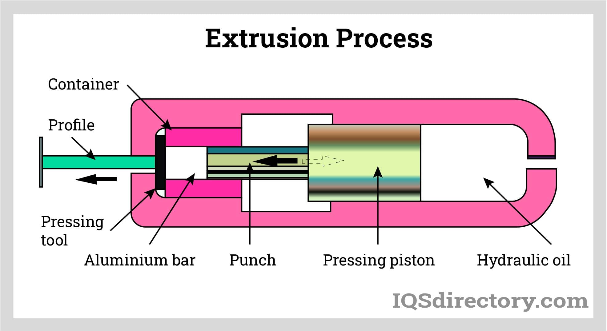
As an example, forward extrusion mainly occurs when the blank is driven to enter into a die with a diameter much smaller than itself. The length increases while the diameter decreases. On the other hand, the backward extrusion process involves subjecting the metal blank to high pressure from an angular punch. Since there is nowhere else for the metal blank to go, it squirts along the outer boundary of the punch and then flows in the backward direction.
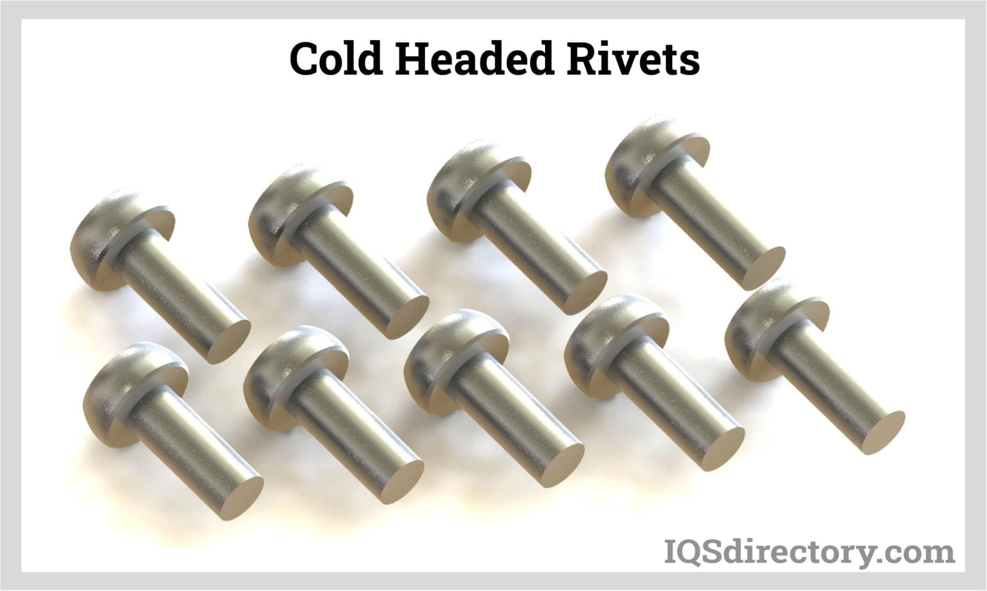
The forward extrusion process is used to make screws, stepped shafts, or bolts, while the backward extrusion process is used in making numerous cylindrical designs and shapes such as sleeves, nuts, and rivets. Just like upsetting, extrusion rearranges the shape of the metal blank; therefore, there is zero loss of material being used. The extrusion process can be either an open or contained form.
Open extrusion means the blank is driven or forced into a die, while the trapped extrusion process is when the blank is wholly contained within a die. The controlled upsetting processes are dependent on the diameters of the wire, and the extrusions processes are based on the area reduction of the blank. This is usually calculated as a percentage and based on the angle of extrusion.
A basic rule for open extrusion is that the percentage of area decrease in one blow should not surpass 30 percent. Always take note that the diameter measurements done before and after extrusion are not used for the direct computation of area reduction.
Open Extrusion
Open extrusion does not confine a part with tools. This allows the extruding part of the tool to be located close to the top side of the die. This maximizes the length that can be extruded on the part.
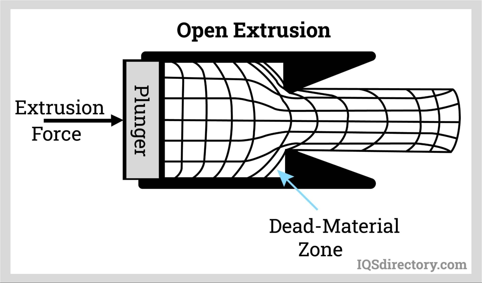
The disadvantage, however, is that open extrusion requires pressure to drive the part through the extruding portion of the tool. If there is too much pressure due to the part not being supported by the tools, buckling will occur, resulting in failure.
Trapped Extrusion
Trapped extrusions are the complete opposite of an open extrusion process. This is because the part must be wholly confined in the tool before it is driven through the extruding part of the tool. This creates room to push much harder to reduce the diameter by about seventy five percent.
A limitation is that the greater part of the tool is grasped to partly make room before extruding so that the length of the extrusion is short and more limited than in an open extrusion process. Trapped extrusion is also called contained extrusion. This process is responsible for why headers produce complicated parts.
The radial extrusion die is often preferred for contained extrusion of the cold headed parts. This is because this form of die decreases die pressure and improves the pattern of flow of the wire as it is driven through the die. With almost all contained extrusion dies, the best results are obtained by making wire that has a larger diameter than the shank that is finished.
The wire size is selected carefully so that the dimensions of the head will be roughly two times the original diameter of the wire. This wire is also extruded to the diameter of the shank and upset to the head dimensions in the customary manner.
Reverse Extrusion
The process of reverse extrusion is defined as the primary process used in making hollow parts such as bushings or nuts. In this method, a pin is driven into the part contained inside the die. There is a significant clearance on the outer pin diameter and the walls of the die. This allows the materials to flow in a backward direction up along the pin. The product of this is an outer form starting to take shape and the starting of an inside channel or hole.
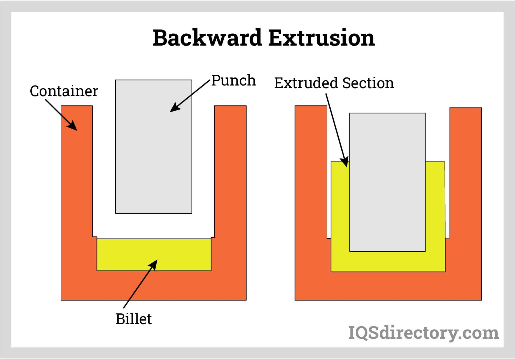
The process of reverse extrusion is also used to make internal drive recesses in many screw heads. The last processes that can be done in cold heading are trimming and piercing. Not all parts will be pierced or trimmed; in fact, the majority of outside threaded screws do not have to undergo the trimming process.
Trimming and piercing are both shearing processes. The force, design, and speed of the tools shear the subject area away. For the parts threaded externally, trimming is exclusively kept for the finishing of a collar or a head shape, often a trimmed hex head. When the inside threaded parts are made, the reverse extrusion process typically occurs on all sides of the part. The blank will contain holes and does not go all the way through on the two sides of the part. A thin web of the material separates the holes.
The final process is the piercing operation. This is when a pin is thrust inside the hole, completely shears the web, and opens a continuous hole through the part. In these two cases, whether it is an outside part that is under trimming or an internal part that is being pierced, there is very little offal. This is the only scrap experienced during the cold heading process, and it is a very small percentage of the total amount of material.
Company address:No. 1560-2 chuangxin 2nd road, songbei district, Harbin.
Mailbox:chen@rainbowtechnology.net


No. 1560-2, 2nd chuangxin road, songbei district, Harbin.
+86-451-51066797
WhatsApp/Mobile : +86-18604505477


