


Screw threads may be formed by rolling either by using some type of thread-rolling machine or by equipping an automatic screw machine or turret lathe with a suitable threading roll. If a thread-rolling machine is used, the unthreaded screw, bolt, or other “blank” is placed (either automatically or by hand) between dies having thread-shaped ridges that sink into the blank, and by displacing the metal, form a thread of the required shape and pitch. The thread-rolling process is applied where bolts, screws, studs, threaded rods, etc., are required in large quantities. Screw threads that are within the range of the rolling process may be produced more rapidly by this method than in any other way. Because of the cold-working action of the dies, the rolled thread is 10 to 20 percent stronger than a cut or ground thread, and the increase may be much higher for fatigue resistance. Other advantages of the rolling process are that no stock is wasted in forming the thread, and the surface of a rolled thread is harder than that of a cut thread, thus increasing wear resistance.
Thread-Rolling Machine of Flat-Die Type
One type of machine that is used extensively for thread rolling is equipped with a pair of flat or straight dies. One die is stationary and the other has a reciprocating movement when the machine is in use. The ridges on these dies, which form the screw thread, incline at an angle equal to the helix angle of the thread. In making dies for precision thread rolling, the threads may be formed either by milling and grinding after heat treatment, or by grinding “from the solid” after heat treating. A vitrified wheel is used.
In a thread-rolling machine, thread is formed in one passage of the work, which is inserted at one end of the dies, either by hand or automatically, and then rolls between the die faces until it is ejected at the opposite end. The relation between the position of the dies and a screw thread being rolled is such that the top of the thread-shaped ridge of one die, at the point of contact with the screw thread, is directly opposite the bottom of the thread groove in the other die at the point of contact. Some form of mechanism ensures starting the blank at the right time and square with the dies.
Thread-Rolling Machine of Cylindrical-Die Type
With machines of this type, the blank is threaded while being rolled between two or three cylindrical dies (depending upon the type of machine) that are pressed into the blank at a rate of penetration adjusted to the hardness of the material, or wall thickness in threading operations on tubing or hollow parts. The dies have ground, or ground and lapped, threads and a pitch diameter that is a multiple of the pitch diameter of the thread to be rolled. As the dies are much larger in diameter than the work, a multiple thread is required to obtain the same lead angle as that of the work. The thread may be formed in one die revolution or even less, or several revolutions may be required (as in rolling hard materials) to obtain a gradual rate of penetration equivalent to that obtained with flat or straight dies if extended to a length of possibly 15 or 20 feet (4.6 or 6 m). Provisions for accurately adjusting or matching the thread rolls to bring them into proper alignment with each other are important features of these machines.
Two-Roll Type of Machine: With a two-roll type of machine, the work is rotated between two horizontal power-driven threading rolls and is supported by a hardened rest bar on the lower side. One roll is fed inward by hydraulic pressure to a depth that is governed automatically.
Three-Roll Type of Machine: With this machine, the blank to be threaded is held in a “floating position” while being rolled between three cylindrical dies that, through toggle arms, are moved inward at a predetermined rate of penetration until the required pitch diameter is obtained. The die movement is governed by a cam driven through change gears selected to give the required cycle of squeeze, dwell, and release.
Rate of Production
Production rates in thread rolling depend upon the type of machine, the size of both machine and work, and whether the parts to be threaded are inserted by hand or automatically. A reciprocating flat die type of machine, applied to ordinary steels, may thread 30 or 40 parts per minute in diameters ranging from about 5⁄8 to 1 1/8 inch(15.875–28.575 mm), and 150 to 175 per minute in machine screw sizes from No. 10 (.190 inch) to No. 6 (.138 inch). In the case of heat-treated alloy steels in the usual hardness range of 26 to 32 Rockwell C, the production may be 30 or 40 per minute or less. With a cylindrical die type of machine, which is designed primarily for precision work and hard metals, 10 to 30 parts per minute are common production rates, the amount depending upon the hardness of material and allowable rate of die penetration per work revolution. These production rates are intended as a general guide only. The diameters of rolled threads usually range from the smallest machine screw sizes up to 1 or 1½ inches (25.4 or 38.1 mm), depending upon the type and size of machine.
Precision Thread Rolling
Both flat and cylindrical dies are used in aeronautical and other plants for precision work. With accurate dies and blank diameters held to close limits, it is practicable to produce rolled threads for American Standard Class 3 and Class 4 fits. The blank sizing may be by centerless grinding or by means of a die in conjunction with the heading operations. The blank should be round, and, as a general rule, the diameter tolerance should not exceed ½ to 2⁄3 the pitch diameter tolerance. The blank diameter should range from the correct size (which is close to the pitch diameter, but should be determined by actual trial), down to the allowable minimum, the tolerance being minus to insure a correct pitch diameter, even though the major diameter may vary slightly. Precision thread rolling has become an important method of threading alloy steel studs and other threaded parts, especially in aeronautical work where precision and high-fatigue resistance are required. Micrometer screws are also an outstanding example of precision thread rolling. This process has also been applied in tap making, although it is the general practice to finish rolled taps by grinding when the Class 3 and Class 4 fits are required.
Steels for Thread Rolling
Steels vary from soft low-carbon types for ordinary screws and bolts, to nickel, nickel-chromium and molybdenum steels for aircraft studs, bolts, etc., or for any work requiring exceptional strength and fatigue resistance. Typical SAE alloy steels are No. 2330, 3135, 3140, 4027, 4042, 4640 and 6160. The hardness of these steels after heat-treatment usually ranges from 26 to 32 Rockwell C, with tensile strengths varying from 130,000 to 150,000 psi (896–1034 MPa). While harder materials might be rolled, grinding is more practicable when the hardness exceeds 40 Rockwell C. Thread rolling is applicable not only to a wide range of steels but for non-ferrous materials, especially if there is difficulty in cutting due to “tearing” the threads.
Diameter of Blank for Thread Rolling
The diameter of the screw blank or cylindrical part upon which a thread is to be rolled should be less than the outside screw diameter by an amount that will just compensate for the metal that is displaced and raised above the original surface by the rolling process. The increase in diameter is approximately equal to the depth of one thread. While there are rules and formulas for determining blank diameters, it may be necessary to make slight changes in the calculated size in order to secure a well-formed thread. Blank diameter should be verified by trial, especially when rolling accurate screw threads. Some stock offers greater resistance to displacement than other stock, owing to greater hardness or tenacity of the metal. The following figures may prove useful in establishing trial sizes. The blank diameters for screws varying from ¼ to ½ are from 0.002 to 0.0025 inch(50.8–63.5 μm) larger than the pitch diameter, and for screws varying from ½ to 1 inch(12.7–25.4 mm) or larger, the blank diameters are from 0.0025 to .003 inch (63.5–76.2 μm) larger than the pitch diameter. Blanks which are slightly less than the pitch diameter are intended for bolts, screws, etc., which are to have a comparatively free fit. Blanks for this class of work may vary from 0.002 to 0.003 inch(50.08–76.2 μm) less than the pitch diameter for screw thread sizes varying from ¼ to ½ inch(6.35–12.7 μm), and from 0.003 to 0.005 inch(76.2–127 μm) less than the pitch diameter for sizes above ½ inch. If the screw threads are smaller than ¼ inch, the blanks are usually from 0.001 to 0.0015 inch(25.4–38.1 μm) less than the pitch diameter for ordinary grades of work.
Thread Rolling in Automatic Screw Machines
Screw threads are sometimes rolled in automatic screw machines and turret lathes when the thread is behind a shoulder so that it cannot be cut with a die. In such cases, the advantage of rolling the thread is that a second operation is avoided. A circular roll is used for rolling threads in screw machines. The roll may be presented to the work either in a tangential direction or radially, either method producing a satisfactory thread. In the former case, the roll gradually comes into contact with the periphery of the work and completes the thread as it passes across the surface to be threaded. When the roll is held in a radial position, it is simply forced against one side until a complete thread is formed. The method of applying the roll may depend upon the relation between the threading operation and other machining operations. Thread rolling in automatic screw machines is generally applied only to brass and other relatively soft metals, owing to the difficulty of rolling threads in steel. Thread rolls made of chrome-nickel steel containing from 0.15 to 0.20 percent of carbon have given fairly good results, however, when applied to steel. A 3 percent nickel steel containing about 0.12 percent carbon has also proved satisfactory for threading brass.
Factors Governing the Diameter of Thread Rolling
The threading roll used in screw machines may be about the same diameter as the screw thread, but for sizes smaller than, say, 3⁄4 inch (19.05 mm), the roll diameter is some multiple of the thread diameter minus a slight amount to obtain a better rolling action. When the diameters of the thread and roll are practically the same, a single-threaded roll is used to form a single thread on the screw. If the diameter of the roll is made double that of the screw, in order to avoid using a small roll, then the roll must have a double thread. If the thread roll is three times the size of the screw thread, a triple thread is used, and so on. These multiple threads are necessary when the roll diameter is some multiple of the work, in order to obtain corresponding helix angles on the roll and work.
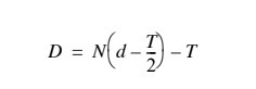
Diameter of Threading Roll
The pitch diameter of a threading roll having a single thread is slightly less than the pitch diameter of the screw thread to be rolled, and in the case of multiple-thread rolls, the pitch diameter is not an exact multiple of the screw thread pitch diameter but is also reduced somewhat. The amount of reduction recommended by one screw machine manufacturer is given by the formula shown at the end of this paragraph. A description of the terms used in the formula is given as follows: D = pitch diameter of threading roll, d = pitch diameter of screw thread, N = number of single threads or “starts” on the roll (this number is selected with reference to diameter of roll desired), T = single depth of thread:
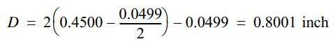
Example: Find, by using above formula, the pitch diameter of a double-thread roll for rolling a ½-inch American standard screw thread. Pitch diameter d = 0.4500 inch and thread depth T = 0.0499 inch.
Kind of Thread on Roll and Its Shape
The thread (or threads) on the roll should be left hand for rolling a right-hand thread, and vice versa. The roll should be wide enough to overlap the part to be threaded, provided there are clearance spaces at the ends, which should be formed if possible. The thread on the roll should be sharp on top for rolling an American (National) standard form of thread, so that less pressure will be required to displace the metal when rolling the thread. The bottom of the thread groove on the roll may also be left sharp or it may have a flat. If the bottom is sharp, the roll is sunk only far enough into the blank to form a thread having a flat top, assuming that the thread is the American form. The number of threads on the roll (whether double, triple, quadruple, etc.) is selected, as a rule, so that the diameter of the thread roll will be somewhere between 1 ¼ and 2 ¼ inches (31.75–57.15 mm). In making a thread roll, the ends are beveled at an angle of 45 degrees, to prevent the threads on the ends of the roll from chipping. Precautions should be taken in hardening, because, if the sharp edges are burnt, the roll will be useless. Thread rolls are usually lapped after hardening, by holding them on an arbor in the lathe and using emery and oil on a piece of hard wood. To give good results a thread roll should fit closely in the holder. If the roll is made to fit loosely, it will mar the threads.
Application of Thread Roll
The shape of the work and the character of the operations necessary to produce it, govern, to a large extent, the method employed in applying the thread roll. Some of the points to consider are as follows:
Diameter of the part to be threaded.
Location of the part to be threaded.
Length of the part to be threaded.
Relation that the thread rolling operation bears to the other operations.
Shape of the part to be threaded, whether straight, tapered or otherwise.
Method of applying the support.
When the diameter to be rolled is much smaller than the diameter of the shoulder preceding it, a cross-slide knurl-holder should be used. If the part to be threaded is not behind a shoulder, a holder on the swing principle should be used. When the work is long (greater in length than two-and-one-half times its diameter) a swing roll-holder should be employed, carrying a support. When the work can be cut off after the thread is rolled, a cross-slide rollholder should be used. The method of applying the support to the work also governs to some extent the method of applying the thread roll. When no other tool is working at the same time as the thread roll, and when there is freedom from chips, the roll can be held more rigidly by passing it under instead of over the work. When passing the roll over the work, there is a tendency to raise the cross-slide. Where the part to be threaded is tapered, the roll can best be presented to the work by holding it in a cross-slide roll-holder.
Tolerances on Wire for Thread Rolling
The wire mills will accept a tolerance specification of plus or minus 0.002 inch (50.8 mm) on the diameter. It is particularly important that this tolerance be maintained on stock used for long screws of small diameter. On screws of short length the material will flow, and if the wire is over size little trouble will be experienced, but in the case of screws having a length greater than ten times their diameter, the material will be confined, and “burning” will take place, if the tolerance is greater than that specified. If the wire is slightly under size, the rolled threads will have a ragged appearance due to the fact that the crest is not fully formed. On screws under the No. 10-24 size, a tolerance of plus or minus 0.001 inch should be adhered to in order to ensure good results.
Speeds and Feeds for Thread Rolling
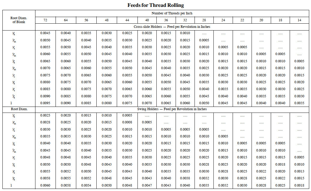
When the thread roll is made from high-carbon steel and used on brass, a surface speed as high as 200 feet per minute can be used. However, better results are obtained by using a lower speed than this. When the roll is held in a holder attached to the cross-slide, and is presented either tangentially or radially to the work, a considerably higher speed can be used than if it is held in a swing tool. This is due to the lack of rigidity in a holder of the swing type. The feeds to be used when a cross-slide roll-holder is used are given in the upper half of the table “Feeds for Thread Rolling;” the lower half of the table gives the feeds for thread rolling with swing tools. These feeds are applicable for rolling threads without a support, when the root diameter of the blank is not less than five times the double depth of the thread. When the root diameter is less than this, a support should be used. A support should also be used when the width of the roll is more than two-and-one-half times the smallest diameter of the piece to be rolled, irrespective of the pitch of the thread. When the smallest diameter of the piece to be rolled is much less than the root diameter of the thread, the smallest diameter should be taken as the deciding factor for the feed to be used.
Company address:No. 1560-2 chuangxin 2nd road, songbei district, Harbin.
Mailbox:chen@rainbowtechnology.net


No. 1560-2, 2nd chuangxin road, songbei district, Harbin.
+86-451-51066797
WhatsApp/Mobile : +86-18604505477